
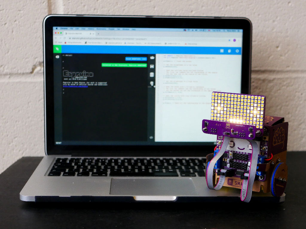
The Smartibot Genius kit includes two extra circuit boards that plug into the Smartibot circuit board and open up more opportunities to learn programming. The LED matrix comprises 144 warm white LEDs and is ideal for displaying text and simple graphics. The sensor board includes two laser time of flight distance sensors and a gesture sensor. This tutorial introduces some simple exercises to learn how to use both of these boards by programming your Smartibot in JavaScript using the Espruino web-based IDE.
Loading JavaScript onto Smartibot using Espruino
To start open up Espruino in Chrome.
Connect to your Smartibot by clicking on the plug symbol at the top left of the screen.

This should bring up a dialogue that asks you to select a port.
If you are using Espruino in the browser only Web Bluetooth will be available:

You should click on this and, select your Smartibot in the pop-up window and click the 'Pair' button (If your Smartibot doesn't appear in the list after a few seconds check that it is powered up and no longer connected to the app - exit the control pad, AI or telepresence mode, or force-close the app to make sure of this):

Once connected to your Smartibot you can load on the code by clicking on the symbol in the middle of the screen that looks like a microchip with an arrow on it:

To load any of these examples copy the code from below, paste it into the white area on the right hand side of the screen (replace any code that is there already) and then click the above symbol. The code should run as soon as it has finished transferring.
All of these examples contain 'comments'. These are bits of text that are included in the code but are not interpreted as instructions by the Smartibot and are instead there to help explain how the code works. You can spot them because they all start with //. You can change or delete them without affecting how the code works but they can be a helpful reminder of what different bits of code do.
Displaying text

The first thing we are going to do is connect the LED matrix (display) to E1 (the connector on the bottom left of the Smartibot circuit board) and get it to display some text. The code below does this by including the necessary libraries, telling the Smartibot that the display is connected to E1, clearing the screen, setting the brightness, setting up the text and position and then sending them to the display.
// We need to include the Smartibot and Smartibot-display libraries
var smarti = require("Smartibot");
var g = require("Smartibot-display").connect(smarti.E1);

g.clear(); //Clear the screen
g.setColor(150); // set brightness - 0..255

// This sends text to the screen in a specific position
g.drawString('Hi',5,2);

// Send what we have setup drew to the screen
g.flip();
Displaying scrolling text

We can show much more text if we get it to scroll across the screen. This example does this by running a function called draw(), which moves the text one pixel left (and then back to the start at the end) each time it is run, over and over again, 20 times each second. It uses a slightly larger font than the standard Espruino one that looks much better on the Smartibot display.
// We need to include the Smartibot and Smartibot-display libraries
var smarti = require("Smartibot");
var g = require("Smartibot-display").connect(smarti.E1);

// We are also going to include the Espruino larger font
require("Font6x8").add(Graphics);

var pos = 0; // a variable to set the horizontal position of the text
var count = 0; // a counter that we will use to count to a set value and then resets to 0 and start counting again

// Put the message you want to display inside the " " below
var message ="Hi, I'm a Smartibot";

function draw(){
// This code makes the tect scroll
if (count < ((message.length*4) + 32)){
 count ++;
}
 else {count = 0;}

pos = 16 - count;

g.clear(); //Clear the screen
g.setColor(150); // set brightness - 0..255
g.setFont6x8(); // set the font to 6x8 size

// This sends the text to the screen in the right horizontal position
g.drawString(message,pos,1);

// Send what we have setup to the screen
g.flip();
}

// Make draw() run every 50 ms (20 times a second)
setInterval(draw, 50);
Drawing a face

As well as text we can draw graphics on the LED matrix display by creating shapes like circles and rectangles in code. The example below does this by making eyes using outlined and filled in circles and a mouth using a filled in rectangle. We can set the brightness for each shape separately, so we can make the eye outlines less bright than the pupils and the mouth. We specify all the positions of all of the shapes using X and Y coordinates relative to the top-left corner of the LED matrix.
var smarti = require("Smartibot");
var g = require("Smartibot-display").connect(smarti.E2);

g.clear(); // Clear the screen

// Set the brightness to a low value
g.setColor(20);

// Make eye outlines using outlined circles
// The first two numbers are the coordinates of the centre
// and the last one is the radius of the circle
g.drawCircle(2,4,2);
g.drawCircle(13,4,2);

// Set the brightness to a high value
g.setColor(250);

// Make the mouth with a filled-in rectangle
// The fist two numbers are the coordinates of one corner
// and the second two are the coordnates of the opposite corner
g.fillRect(6,7, 9,8);

// Make the pupils with tiny filled-in circles
g.fillCircle(2,4,0);
g.fillCircle(13,4,0);

g.flip(); // Send all the instructions to the display
Displaying the measurements from the distance sensors

We can add the sensor board to connection E2 and then display the distances each of the two distance sensors is measuring, on the LED matrix, using this example. It also has a function that runs over and over again at 20 times a second, but this time it is called measure() and it reads the distances the two sensors are measuring, in millimetres, converts them to centimetres (so they take up fewer digits) and then displays them. It uses another different font, one that displays numbers better than the standard one.
// We need to include the Smartibot, Smartibot-display
// and Smartibot-distance libraries
var smarti = require("Smartibot");
var g = require("Smartibot-display").connect(smarti.E1);
var dist = require("Smartibot-distance").connect(smarti.E2);

// We are going to use the 4x5 font
require("Font4x5").add(Graphics);


function measure(){

// We are read the two sensors, divide by 10 to convert from mm to cm
// and use Math.floor to round the numbers down to the nearest cm
right = Math.floor(dist.getRight()/10);
left = Math.floor(dist.getLeft()/10);

g.clear(); //Clear the screen
g.setColor(100); // set brightness - 0..255
g.setFont4x5(); //

// We are gong to display the two distances on opposite sides of the screen
g.drawString(left,0,2);
g.drawString(right,8,2);


// Send what we have setup drew to the screen
g.flip();
}

// Run measure every 50 ms (20 times a second)
setInterval(measure,50);
Displaying gestures from the gesture sensor
The sensor board also includes a gesture sensor, positioned in the middle. If you wipe your hand a few centimetres in front of it it should be able to detect the direction you were moving. This example displays any gestures the sensor detects on the display.
var smarti = require("Smartibot");
var dist = require("Smartibot-distance").connect(smarti.E1);
var g = require("Smartibot-display").connect(smarti.E2);

setInterval(function() {
  var gesture = dist.getGesture();
  // The if statement checks if a gesture has been detected
  if (gesture) {
  g.clear(); // Clear the screen
  g.drawString(gesture,1,2); // Write the name of the gesture detected
  g.flip(); // Send to the display
  }
}, 500); // The code runs every 500 ms (2 times a second)
Next Steps
Hopefully these examples will help you get up and running with your own project ideas (if you make something cool we'd love to see - hello [at] thecraftyrobot [dot] net). You can find some more complicated project examples below:

To make Smartibot avoid walls and visualise the distance measurements on the LED matrix
The full list of all of the graphics functions you can use in Espruino can be found here and code snippets for all the basic functions available on the Smartibot are here.